 ParaCrux
Case study · From the lab · 29 September 2026
The rod looked right on the drawing. Then we loaded it.
We asked an AI agent to run the CR-110 connecting rod through SOLIDWORKS Simulation and judge it against a written company standard. It found the small end short in tension. It changed the design, rebuilt it and ran it again until it passed, then took weight out where the steel wasn't working.
Lab work. Simulation checks are not yet a feature of the Agent you can buy. This page says which is which.
THE BRIEF
“Check CR-110 against our standard. Fix what fails, then take out weight where it isn't working.”The case study in 82 seconds
Loaded, judged,
changed, checked again.
Narrated by Tom. The numbers and contour plots come from the run below; the isometric drawings are illustrations.
Two load cases, one standard.
The rod body only, in AISI 4340 Steel, normalized. The loads are our assumption for a small single-cylinder engine, and every report says so.
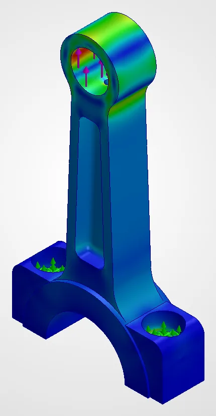
LC1 · firing
28 kN compression
The gudgeon pin pushes on the lower half of the small-end bore. The rod's half of the big-end bore is held.
LC2 · inertia at overrun
14 kN tension
The pin pulls on the upper half of the bore. The load goes out through the two bolt-head seats, into the bolts and the cap.
Standard · PCX-ENG-001 rev A
FoS ≥ 2.0 on yield
Also FoS ≥ 3.0 on ultimate, deflection ≤ 0.1 mm and at least two elements through the thinnest wall. Fatigue is listed and left open.
What it found in rev B.
Measured on a 91k-node second-order mesh. Stress is read outside a 3 mm zone around each fixture, where a rigid hold creates peaks that aren't real.
- FAIL · LC2The small-end eye is short in tension: 395.4 MPa, factor of safety 1.80.
The 5 mm wall around the Ø18 bore bends as the pin pulls. A curved-beam hand check gives about 390 MPa, so this is the part, not the mesh. PCX-ENG-001 asks for 2.0.
- PASS · LC1Firing peaks where the oil hole breaks into the web pocket: 267.9 MPa, factor of safety 2.65.
The Ø3 drilling leaves thin walls in a 5 mm web. It passes, but it is why the web could not be thinned.
- OPENBuckling and fatigue were not judged.
This seat has SOLIDWORKS Simulation Standard, so the solver refused the buckling study, and the report says so rather than skipping it. A con rod is fatigue-critical; a static pass is not fitness for service.
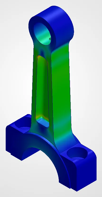
Where the steel is working, and where it isn't.
Peak stress on the faces each feature made, as a share of the allowable 355 MPa (yield ÷ 2.0), across both load cases.
- small end bore111% LC2-inertia
- small end102% LC2-inertia
- oil hole96% LC2-inertia
- blend small end78% LC2-inertia
- pocket floors76% LC1-firing
- web69% LC1-firing
- pockets66% LC1-firing
- pocket corners66% LC1-firing
- shank47% LC2-inertia
- blend big end33% LC1-firing
How the loop ran.
Six steps. Each run leaves a results bundle you can open, check and run again.
- 01
Write the study once
Loads, fixtures and faces go in a study file. Faces are picked by the feature that made them and their shape, with an expected count, so a model change cannot quietly move a load.
- 02
Run it on a copy
The agent starts its own hidden SOLIDWORKS, copies the part, removes the bearing cap from the copy and runs each load case in SOLIDWORKS Simulation. The original is never saved.
- 03
Judge it against the standard
Each result is checked against a written standard: factor of safety on yield and ultimate, deflection, and elements through the thinnest wall. Anything it cannot measure is marked open, never passed.
- 04
Find the idle material
Stress is read on the faces each feature made. A feature working well below the allowable stress is a place to take material out; one above it needs more.
- 05
Change, rebuild, re-run
It changes only dimensions the study allows, within stated bounds. If the model will not rebuild it tries half the step, then gives up and says so.
- 06
Report and compare
Every run is a results bundle. The ParaCrux app turns one into a printable report, or several into a comparison, in your own template.
What it changed, and why.
Only dimensions the study allows could move. The bores, bearing widths, centre distance, bolt counterbores and balance pad were locked.
V1 · 575.7 g · passes PCX-ENG-001
- Small-end eye diameter: 28 → 31 mm
- Shank width at the big end: 24 → 22 mm
- Bolt boss depth: 20 → 18 mm
The agent's reasons
D2@SK-SMALL-END to 31 mm: SMALL-END-BORE reaches 395 MPa in LC2-inertia, 111% of the allowable stress. Add material here.
D1@SK-SHANK to 22 mm: Its busiest feature, SHANK, works at 47% of the allowable stress. Material here is mostly idle.
D1@BOLT-BOSSES to 18 mm: Its busiest feature, M8 CBORE, works at 22% of the allowable stress. Material here is mostly idle.
V2 · 568.6 g · passes PCX-ENG-001
- Small-end eye diameter: 28 → 31 mm
- Shank width at the big end: 24 → 22 mm
- Bolt boss depth: 20 → 17 mm
The agent's reasons
D1@BOLT-BOSSES to 17 mm: Its busiest feature, MIRROR M8 CBORE, works at 22% of the allowable stress. Material here is mostly idle.
Rejected: Big-end outer diameter — the model would not rebuild at that size, so the change was dropped rather than forced.
Set your own standard.
PCX-ENG-001 is our example. Yours might ask for more margin, or less deflection. Move the limits; the results are the measured ones and don't change.
| Design | Mass | Peak firing, 28 kN compression | Peak inertia at overrun, 14 kN tension | Verdict |
|---|---|---|---|---|
| baselineAs released | 584.1 g | FoS 2.650.054 mm | FoS 1.800.081 mm | Fail |
| V1Iteration 1 | 575.7 g | FoS 2.550.088 mm | FoS 2.310.076 mm | Pass |
| V2Iteration 2 | 568.6 g | FoS 2.540.088 mm | FoS 2.340.077 mm | Pass |
Lightest design that meets your limits: V2, 568.6 g. Stress is measured outside a 3 mm zone around the fixtures. Fatigue is not judged here.
Rev B against V2.
15.5 g lighter overall, and the small end now meets the standard. Same loads, same fixtures, same mesh settings.
The trade it made. The narrower shank lets the rod shorten more under firing: 0.054 mm became 0.088 mm. That is inside the 0.1 mm limit, but it uses 88% of it. Set the deflection limit to 0.08 mm in the table above and both redesigns fail it.
| baseline | V2 | |
|---|---|---|
| Mass (rod and cap) | 584.1 g | 568.6 g |
| Peak firing, 28 kN compression | 267.9 MPa · FoS 2.65 · 0.054 mm | 279.3 MPa · FoS 2.54 · 0.088 mm |
| Peak inertia at overrun, 14 kN tension | 395.4 MPa · FoS 1.80 · 0.081 mm | 303.7 MPa · FoS 2.34 · 0.077 mm |
| PCX-ENG-001 | Fails | Passes, fatigue and buckling open |
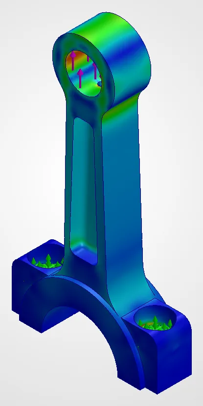
Reports in your template.
Each run is a results bundle: numbers, contour images and every assumption. The ParaCrux app imports it, renders a printable report or a comparison of runs, and saves it as a new file. Put your own template in the workspace and the report takes your layout and name.
Both are real output from this run, rendered by the app. To make it yours, save the report template as simulations/report-template.html in your workspace and edit the layout, colours and name. The slots in double braces are filled for you.
- Verdict against your standard, criterion by criterion, with the margin
- Each load case: fixtures, loads, evaluated and peak stress, deflection, reactions
- Stress by feature, so you can see what is working and what is idle
- Provenance: SOLIDWORKS 34.4.1, Simulation build, source file hash, run time
- Open items listed, never left out: here, fatigue and buckling
What it couldn't check.
Written into every report, in the same words.
- Design loads are assumed for a single-cylinder engine with a Ø38 crankpin and Ø18 gudgeon pin: 28 kN peak firing compression, 14 kN peak inertia tension at overrun. Replace them with measured engine data before relying on the result.
- Pin loads are bearing loads with a sinusoidal distribution over the loaded half of each bore.
- The rod half of the big-end bore is fixed for the firing case. The two bolt-head seats are fixed for the inertia case. Rigid fixtures raise stress next to them, so stress is evaluated outside a 3 mm zone and the unfiltered peak is reported separately.
- Linear elastic, small displacement, room temperature, no bolt preload, no press-fit of the small-end bush.
- Material properties are read from the SOLIDWORKS material library entry assigned to the part.
- The solver refused this study type (swsRunAnalysisErrorAuthorizationFailed). Buckling needs a SOLIDWORKS Simulation Professional or Premium licence.
Prepared, not certified
The agent prepares. Your engineer verifies and decides. A linear static run is evidence for review. It does not certify a part, replace a fatigue assessment or carry an engineer's signature. Adopting any change is your decision and your responsibility.
Read section 5 of the termsWhat ships today, and what's still in the lab.
If it isn't in the left column, you can't buy it yet.
Available In the Agent today
- Inspect features, dimensions, configurations and properties of the open model
- Propose dimension changes that you review in a worksheet before anything runs
- Run changes on copies and check the native and STEP outputs; your original is kept
Lab Not yet for sale
- SOLIDWORKS Simulation studies run by the agent, on your licence and your workstation
- Results judged against your written standard, with open items listed
- Suggest, rebuild and re-run loops, with reports and comparisons in the app
Which part would you want checked first?
Tell us the part family, the load cases you check today and the rules you check them against. We'll tell you plainly whether it's close, a long way off, or something we won't do.
Please don't attach confidential models. If there's a fit, we'll arrange a proper channel.