 ParaCrux
From the lab · A complex assembly, start to finish
ScoutCrux 500.
A folding drone, designed, checked, then changed.
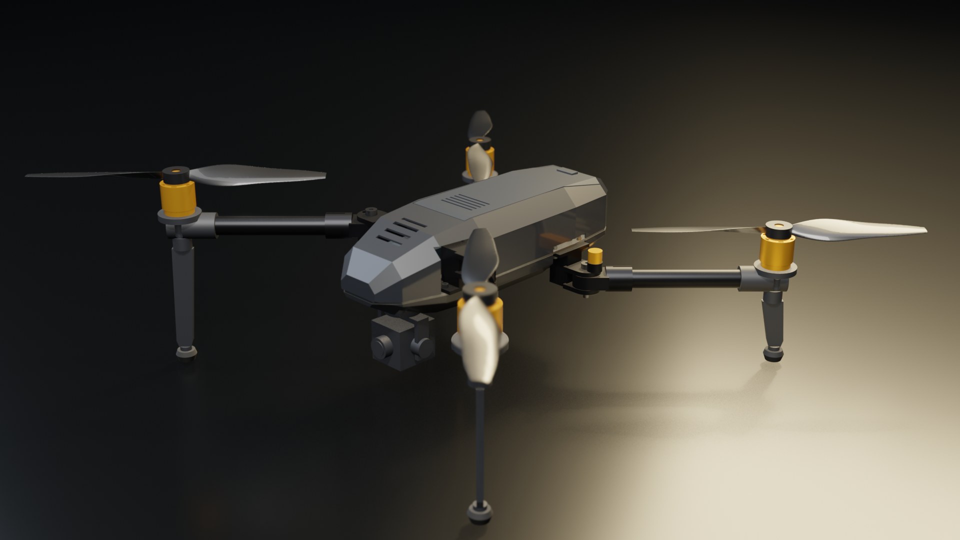
We gave an AI agent a written brief for a folding camera drone. It sized the parts, built 29 parts and 112 components in SOLIDWORKS, checked them, drew them, and opened the assembly in ParaCrux. Then the brief changed to 650 mm, and it changed the design through its parameters instead of scaling it.
Lab work. The agent drove SOLIDWORKS through its API in our lab; building assemblies like this is not yet a shipping Agent feature. The drone has not been built or flown.
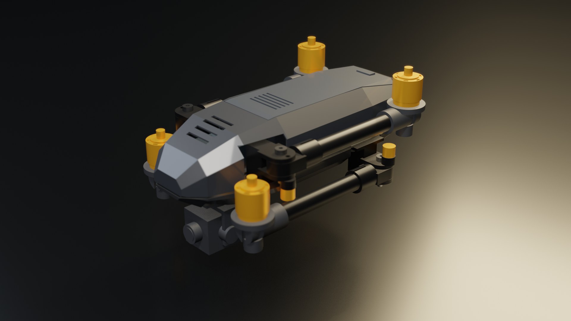
This is the CAD itself in the ParaCrux Viewer: both SOLIDWORKS assemblies, converted from their STEP exports with every face and edge kept. Bought-in parts (motors, propellers, battery, flight controller, gimbal) are envelopes from published dimensions, not supplier models.
ParaCrux Viewer: installation, Vault sharing and configurations ↗
The same viewer, on your website.
The model above is the ParaCrux Viewer: the desktop app's renderer, packaged as one web component. Two lines put it on any page.
<script type="module" src="https://paracrux.com/embed/v0/paracrux-viewer.js"></script>
<paracrux-viewer src="/models/sc-500.deployed.scene.json" auto-rotate></paracrux-viewer>Preview (v0): the element and its file format may still change. To put your own models on your website, tell us what you need.
Watch the whole job.
Tom narrates the brief, the build, the checks and the change. Jump to any chapter; English captions are optional.
The brief, and how each version did.
Every number is read from the CAD or the calculation record. Two items stay open until there is supplier data or a bench test.
| ID | Requirement | ScoutCrux 500 | ScoutCrux 650 |
|---|---|---|---|
| R01 | Motor diagonal | 500.0 mm Pass | 650.0 mm Pass |
| R02 | Gross mass incl. 90 g harness · with the full payload allowance | 1.91 kg · 2.05 kg at 250 g Flagged | 2.52 kg · 2.90 kg at 500 g Pass |
| R04 | Propeller discs clear each other and the body | gap 99.6 · body 24 mm Pass | gap 129.4 · body 57 mm Pass |
| R05 | 2:1 static thrust at gross mass | ≥ 9.8 N per rotor Open | ≥ 14.7 N per rotor Open |
| R06 | 12 min hover on 80 % of the pack (estimate) | 13.1 min Estimate | 12.7 min Estimate |
| R07 | Motor deflection ≤ 0.75 mm, tube + hinge | 0.38 mm · 16 × 1.0 Pass | 0.57 mm · 22 × 1.5 Pass |
| R09 | CG within ±10 mm of centre (chosen camera · full allowance) | 2.2 · 4.3 mm Pass | 4.2 · 8.6 mm Pass |
| R11 | Camera clears ground at full foot stroke | 13 mm Pass | 16 mm Pass |
| R12 | Folded into 350 × 220 × 220 | 266 × 164 × 139 Pass | 384 × 171 × 146 Fail |
| R13 | Change rebuilds with no broken mates | — | 0 mate errors Pass |
R05 needs a measured thrust curve for the exact motor, propeller and voltage. R06 is a momentum-theory estimate (figure of merit 0.6, drive efficiency 0.8), not a flight result. R02 is flagged for the 500: with the chosen 113 g camera module it is 1.91 kg, but a full 250 g camera would take it 46 g over. R12 fails for the 650: folded, it is 384 mm long, so it needs a longer case or a two-piece arm.
Built from the brief, not from a template.
Global variables drive the parts that change. Mates use each part's own planes and axes, never a picked face.
- 01
Size it first
Thrust per rotor, arm deflection with a hinge allowance, hover power and landing load, before any geometry.
- 02
Loft the body
Seven faceted stations, ruled lofts between them, split into PC/ABS upper and lower shells around a 2 mm aluminium plate.
- 03
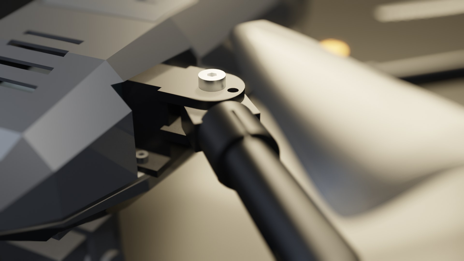
Make the arms fold
A machined clevis, shoulder screw, bronze bushes and an index plunger that locks each arm open or closed.
- 04
Draw it
GA with a parts list and balloons, the folded layout, the arm module, and manufacturing drawings with a DXF for the plate.
The checks found real problems.
Interference detection and the mass check failed on the first pass. Each fix was made in the model, then everything was checked again.
- The battery bay cut the tail off the upper shell
The shell became two bodies; the bay was shortened and narrowed.
- 2.10 kg against a 2.0 kg limit
Clevis, root and pod lightened, shells to 1.3 mm, plate windowed: 1.82 kg. With the 90 g harness and a full 250 g camera it is still 46 g over, so R02 is flagged: the usable camera allowance is 204 g until the structure loses 46 g.
- The clevis flanges ran through the shells
Wider hinge windows and a relief notch over the rear hardware.
- The battery-cover latch reached into the battery
The latch now starts at the cover's inside face.
- The 650 buried the motor-screw heads
The pocket depth was a plain number. It now follows the tube size.
- The 2814 motor's wider pattern put a screw on the tube end
The tube stop now follows the motor's hole pattern.
Final state, both designs: 0 mate errors and no unexpected interference. The remaining overlaps are modelled thread engagements (shoulder screws in the tapped lugs, motor screws in the motor base).
Then the brief changed.
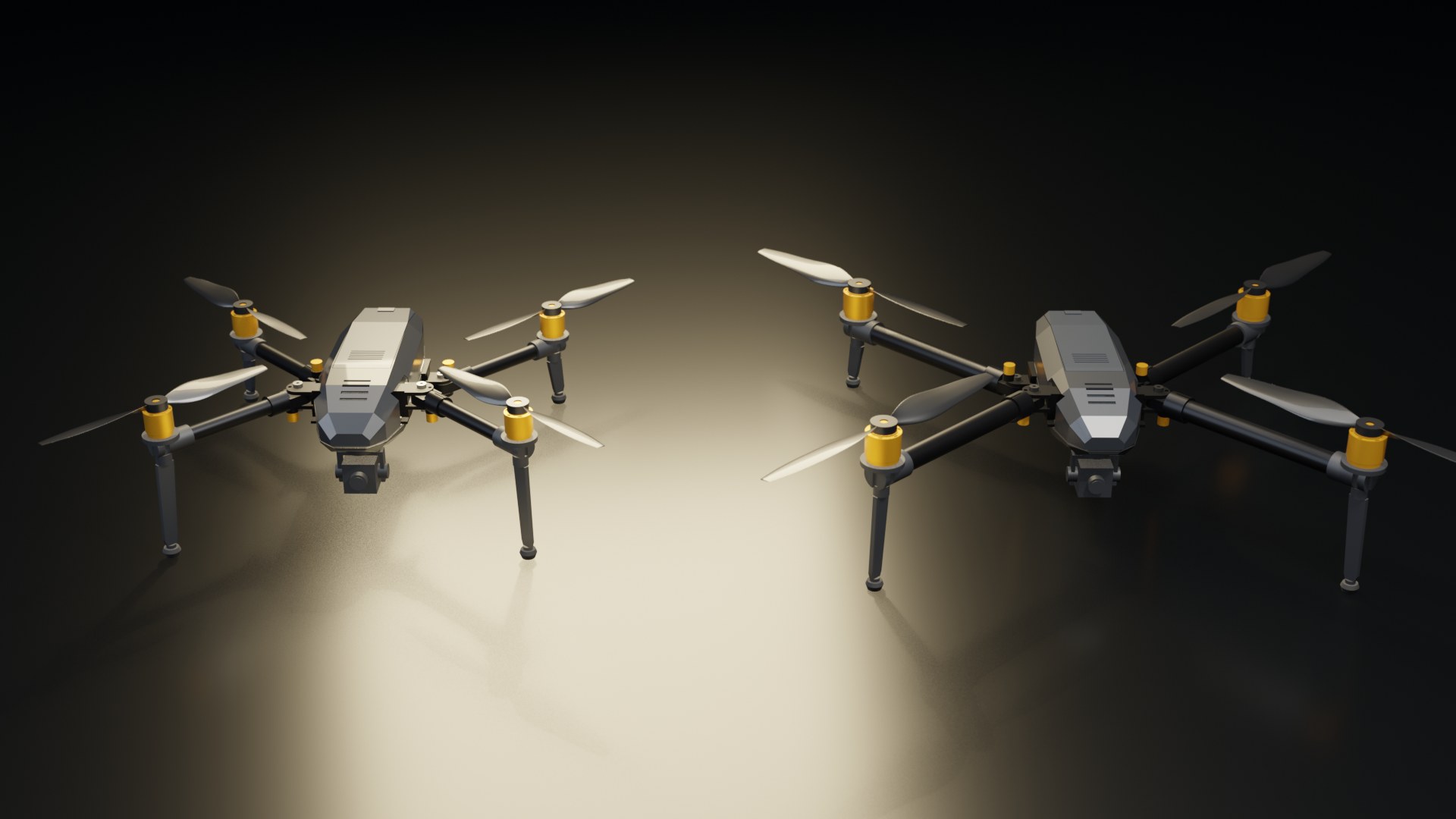
650 mm, 3 kg, a 500 g camera allowance. Keep the camera interface and the electronics pattern. Scaling would have been wrong.
| Item | 500 | 650 | How it changed |
|---|---|---|---|
| Arm tube | 16 × 1.0, L 129.0 | 22 × 1.5, L 202.5 | Global variables OD, ID, LEN |
| Motor | 2216 class, 16 × 19 | 2814 class, 19 × 25 | Catalogue swap; pod pattern PAT_A, PAT_B |
| Propeller | 10 × 4.5 | 13 × 5.5 | Catalogue swap |
| Battery | 4S 5000 mAh | 6S 4500 mAh | 6S 5000 refused: 52 mm tall, bay allows 38.7 |
| Centre body | Unchanged: shells, plate, clevises, camera cassette | Retained by the brief | |
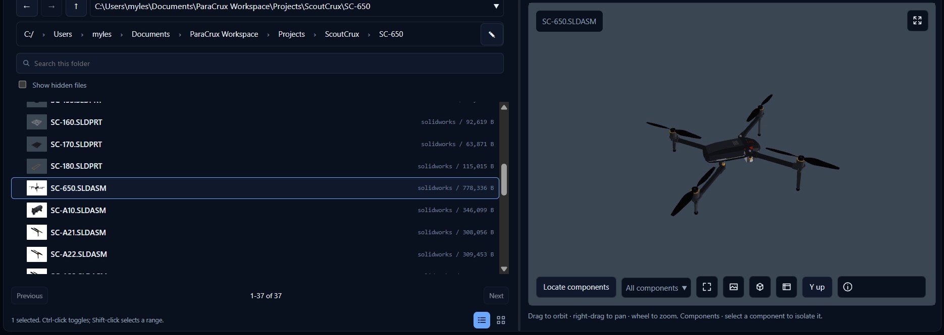
Opened in ParaCrux.
The desktop app reads the native SOLIDWORKS assembly directly: a live preview, every component, and the custom properties, including which design it was copied from.
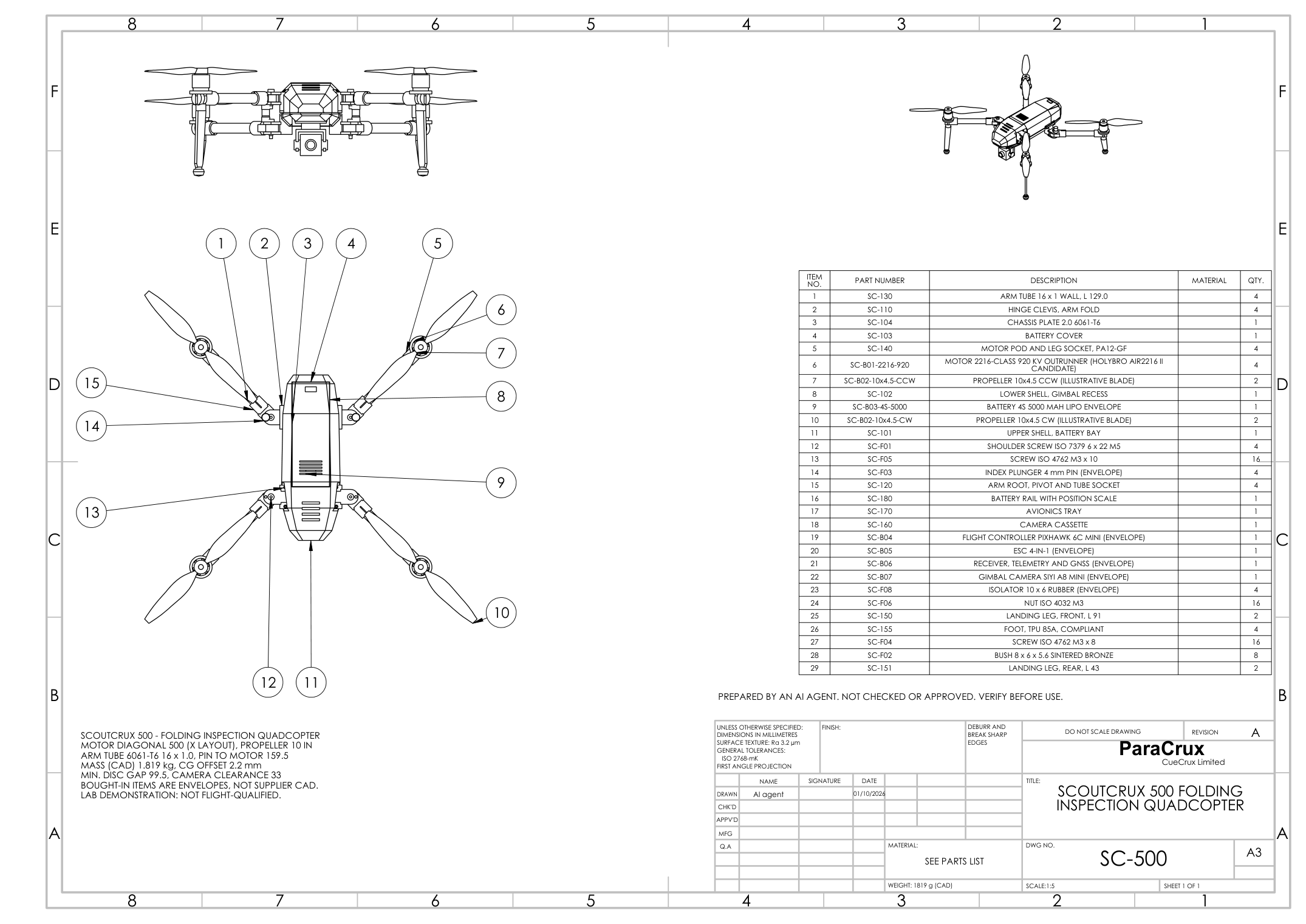
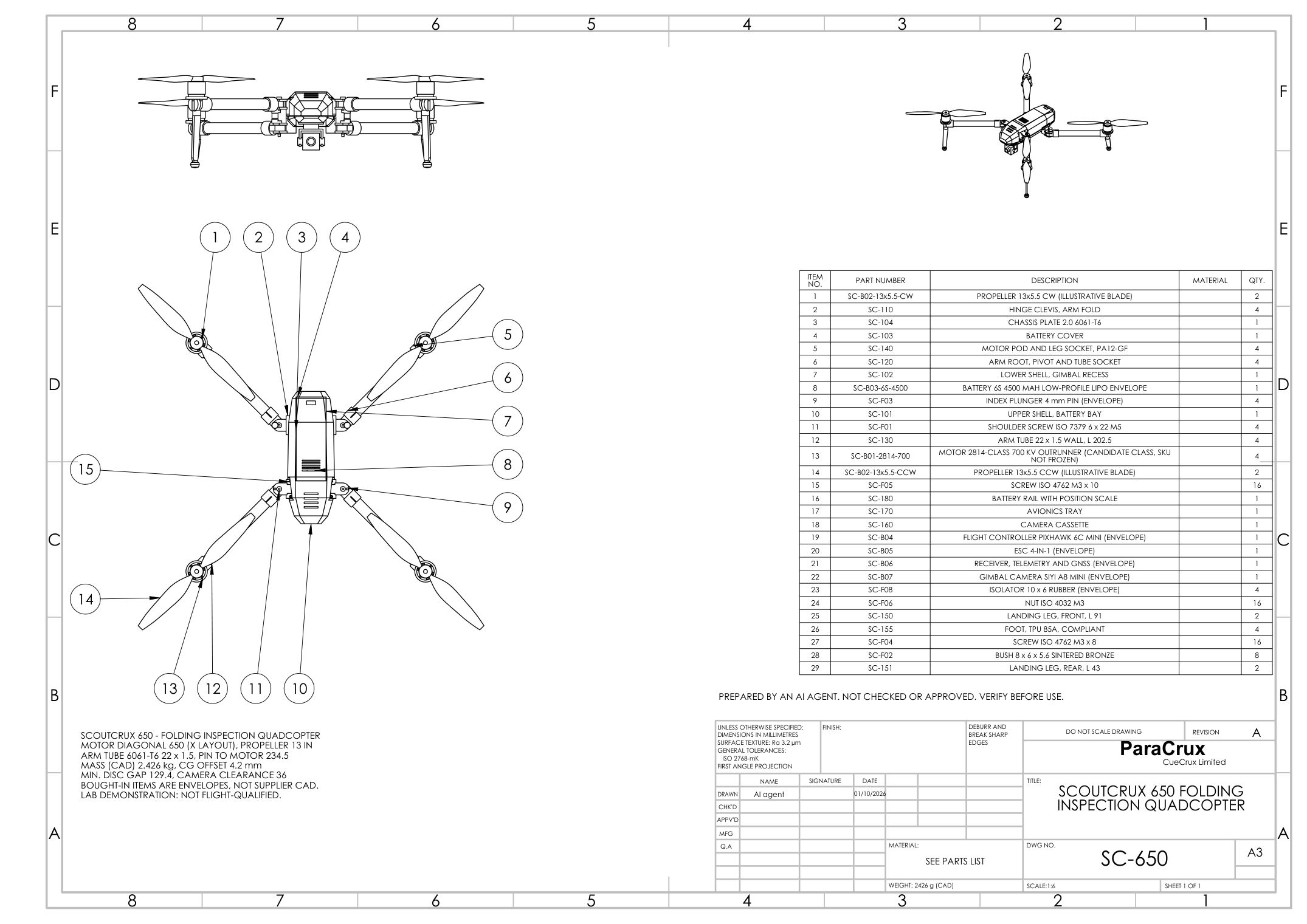
Drawings for both.
Native SLDDRW and PDF, populated from the models' custom properties.
What this demonstrates, and what it doesn't.
An agent can carry a brief through sizing, a complex parametric assembly, honest checks, drawings and a reasoned design change, and say which requirements are still open. It does not show a flight-ready aircraft: thrust, vibration, joints and landing need bench and flight tests, and the bought-in parts are envelopes until supplier CAD is checked. The film is edited and retimed: the SOLIDWORKS footage is a frame-by-frame capture of the real session, not a real-time completion claim.
See what the Agent ships today →Back to all demos →