 ParaCrux
From the lab · Demo set two · Modelling to a standard
TideCrux 100.
An underwater ROV, built to a feature standard.
ScoutCrux showed an agent carrying a brief through to a changed design. TideCrux asks whether the model itself is any good. An AI agent built a harbour-inspection ROV in SOLIDWORKS 2026 through its API, to a written modelling standard: fully defined sketches with named dimensions, the right feature for each job, and parts from the ParaCrux libraries. Then it audited every part, checked the assembly and drew it.
Lab work. The agent drove SOLIDWORKS through its API in our lab; building assemblies like this is not yet a shipping Agent feature. The ROV has not been built, pressure-tested or sea-trialled, and the bought-in thrusters, lights and camera are envelope models.
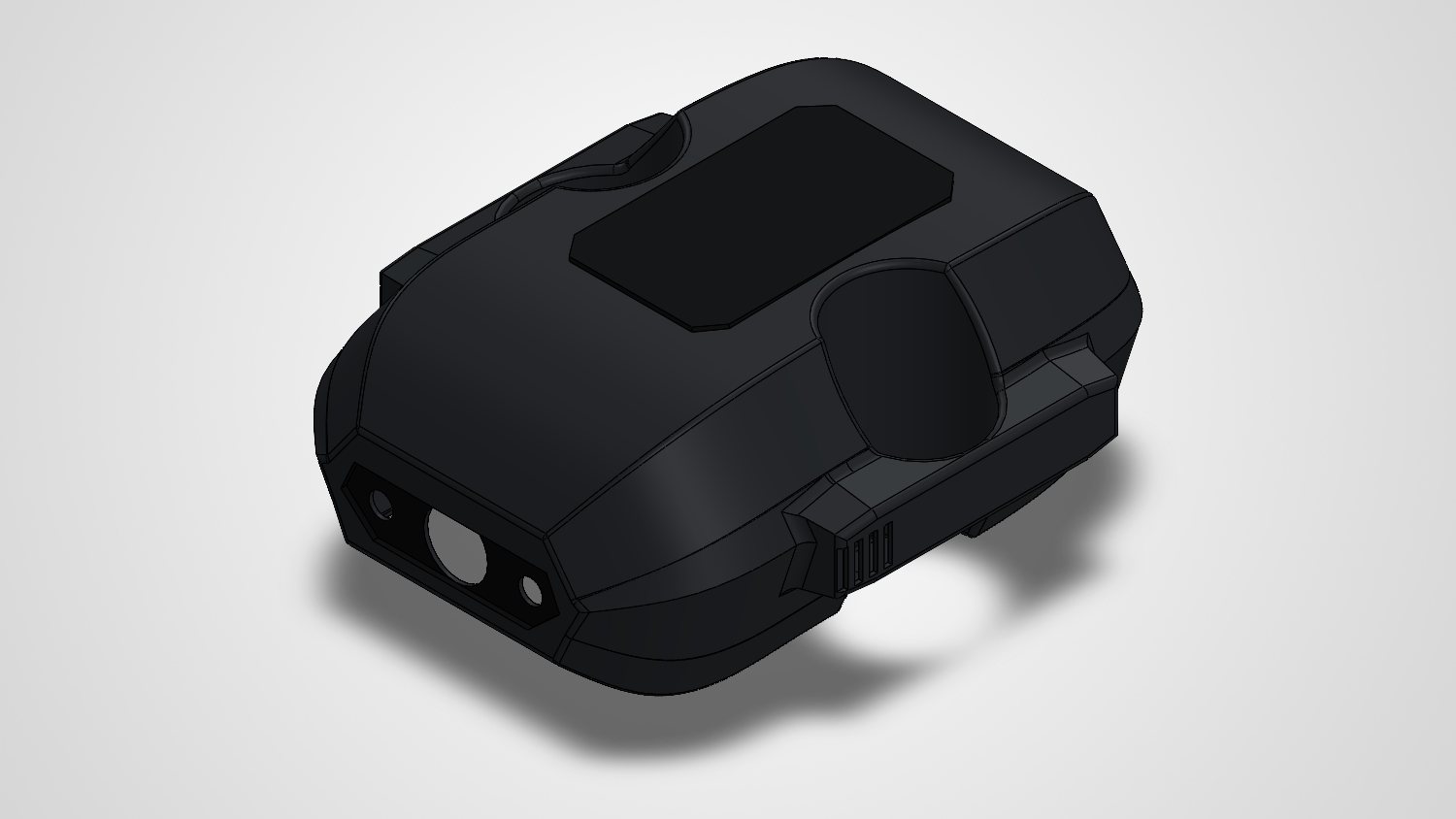
This is the CAD itself in the ParaCrux Viewer, converted from the SOLIDWORKS STEP export with every face and edge kept. Bought-in parts are envelopes from nominal dimensions, not supplier models.
The brief.
A port authority dive team wants a two-person-portable ROV to inspect quay walls, pile caps and moorings down to 100 m in tidal current, with a tilting camera, two lights and a replaceable battery. A fictional brief, sized by hand calculation before any geometry.
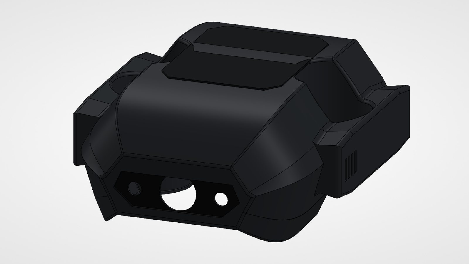
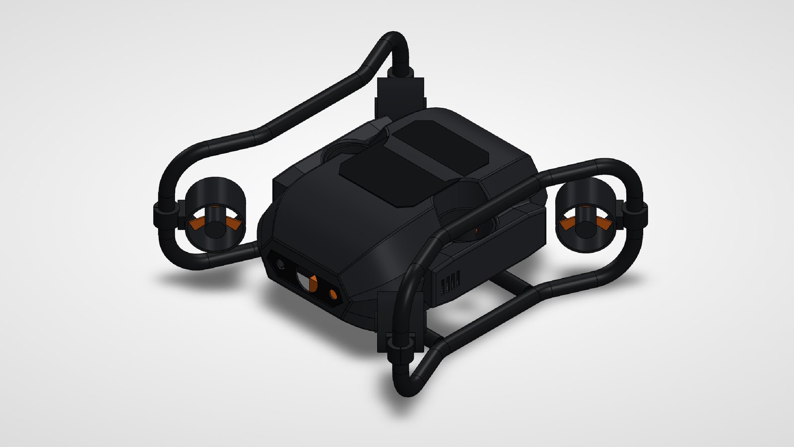
The concept was approved, then frozen into one parameter file. Changing a value there is the only way to change the design, for TideCrux 100 and for the 300.
Sketches that say what they mean.
Every sketch is fully defined with centrelines, relations and named driving dimensions from the origin and datums. No Fixed relations, anywhere. SOLIDWORKS reports the definition state after every sketch closes, and the agent logs it.
The frame is driven, not drawn.
The side frame's 3D bend path is dimensioned to planes from global variables. Change one and the bends, the fillets and the cut length follow. The housing tube's wall follows the pipe schedule through equations, which is how the 300 m change gets a thicker wall without anyone redrawing it.
skid_droprail_risehug_half_widthhug_half_lengthcorner_half_widthcorner_half_lengthbend_clrtube_odtube_wall
Each feature earns its place.
Hole Wizard for hardware holes, patterns and mirrors for repeats, and the feature a manufacturer would recognise for each part: a moulding, a bent tube, a profile, a folded blank, a turned cap.
- 01 · TC-101 fairing
Loft and shell
Lofted through 6 symmetric stations, each a fully defined sketch, then shelled to 3 mm and left open underneath. Decorative bosses go on after the shell so they cannot collapse it.
- 02 · TC-101 fairing
Drafted bosses and sponsons
A moulded part needs draft. The sponson is drafted 9° and mirrored; the screw bosses are drafted 1° and run up to the inside of the skin.
- 03 · TC-101, TC-302, TC-401
Hole Wizard, at a located position
M3 × 0.5 tapped holes in the bosses: one hole dimensioned to 90 and 100 mm, then mirrored twice. 8 M10 × 1.5 penetrator ports on a 64 mm pitch circle, by dimension, then patterned.
- 04 · Fairing, end cap, tray, spider
Patterns and mirrors for repeats
Vents as a linear pattern of 4 mirrored to port, penetrator ports as a circular pattern, tray clamp holes patterned then mirrored front to rear and side to side, and one spider spoke patterned to three.
- 05 · TC-201 side frame
3D-sketch bent-tube sweep
Bend points are dimensioned to planes from global variables, sketch fillets at the 65 mm bend radius (2.6 D) are tied to bend_clr by equations, and a thin 25 × 2.0 circular sweep follows the path. Swept volume 195,122.8 mm³ against 195,121.8 mm³ from πr²L.
- 06 · TC-202 cross member
ParaCrux structural member
The straight cross members are structural members from the ParaCrux EN 755 aluminium round-tube profile, 25 × 2.0, so they come out in a cut list. Volume 51,157.7 mm³, matching the profile exactly.
- 07 · TC-401 chassis tray
Sheet metal with a flat pattern
A 3 mm 6061-T6 base flange from an open U profile, with its flat pattern and a DXF of the blank for cutting.
- 08 · TC-302, TC-303
Revolved caps with real seal glands
End caps revolved with two radial O-ring glands each and a lead-in chamfer. A 3.53 mm section in a 2.79 × 4.7 mm gland gives 21.0 % squeeze and 74.6 % fill: screening values, to be confirmed against ISO 3601-2.
| Bend | L, straight (mm) | R, rotation (°) | A, angle (°) | Arc (mm) |
|---|---|---|---|---|
| 1 | 77.0 | 0.0 | 90.0 | 102.1 |
| 2 | 74.0 | -90.0 | 23.2 | 26.3 |
| 3 | 193.3 | 0.0 | 23.2 | 26.3 |
| 4 | 74.0 | 90.0 | 90.0 | 102.1 |
| 5 | 77.0 | 0.0 | 90.0 | 102.1 |
| 6 | 74.0 | -90.0 | 23.2 | 26.3 |
| 7 | 193.3 | 0.0 | 23.2 | 26.3 |
| 8 | 74.0 | 90.0 | 90.0 | 102.1 |
An audit that has to catch something.
After the build, an auditor opens every part and checks it against the standard: definition, Fixed relations, feature names, Hole Wizard use, patterns and mirrors. A deliberately bad part goes through with them. If the audit cannot catch that, its clean results mean nothing.
| Part | Sketches | Modelling features | Hole Wizard | Patterns | Mirrors | Equations | Findings |
|---|---|---|---|---|---|---|---|
| TC-101 | 14/14 | 22 | 1 | 1 | 4 | – | None |
| TC-201 | 1/1 | 1 | – | – | – | 41 | None |
| TC-202 | 1/1 | 1 | – | – | – | 2 | None |
| TC-301 | 1/1 | 1 | – | – | – | 6 | None |
| TC-302 | 1/1 | 4 | 1 | 1 | – | – | None |
| TC-303 | 2/2 | 3 | – | – | – | – | None |
| TC-304 | 1/1 | 1 | – | – | – | 4 | None |
| TC-401 | 1/1 | 5 | 1 | 1 | 2 | – | None |
| TC-402 | 2/2 | 2 | – | – | – | – | None |
| TC-501 | 2/2 | 4 | 1 | – | 1 | – | None |
| TC-502 | 4/4 | 4 | – | – | – | – | None |
| TC-503 | 2/2 | 3 | – | 1 | – | – | None |
| TC-B01 | 3/3 | 4 | – | 1 | – | – | None |
| TC-B02 | 1/1 | 1 | – | – | – | – | None |
| TC-B03 | 1/1 | 1 | – | – | – | – | None |
| TC-B10 | 1/1 | 1 | – | – | – | – | None |
Round cuts that are not hardware holes.
The rule says hardware holes come from Hole Wizard. Every other round cut is listed for review with its reason, rather than hidden or forced through Hole Wizard.
- TC-101 · Thruster tunnelsflow opening for the vertical thrusters (not a fastener hole)
- TC-101 · Camera window boreoptical opening behind the visor
- TC-101 · Light boresoptical openings for the LED modules
- TC-303 · Dome boreoptical opening for the camera dome
- TC-402 · Housing cradlesaddle seat concentric with the housing (not a hole)
- TC-502 · Duct seat cutthruster duct seat (not a fastener hole)
The logs keep the failures.
Every stage is recorded and logged, and runs are appended, never overwritten. These went wrong first and were fixed in the model.
- The first hull run failed to mirror the vents
It also left the vent-slot sketch under-defined. The second run fixed both, and the log keeps the failed run.
- The first bend path had no solution
The sweep had zero volume and the part saved with errors. The path was rebuilt from the same named variables until it solved. It never fell back to Fixed points.
- End-cap and dome profiles were under-defined
Three sketches on the first housings run, two on the second. Relations and named dimensions were added until all were fully defined.
- The tray's clearance holes would not go in
The M5 Hole Wizard step failed on three chassis runs before the hole was located on the tray, then patterned and mirrored.
- Interference detection failed three times
The tray was narrowed to clear the vertical-thruster tunnels and the clamps moved so each lands under the tray. The fourth run found only the designed O-ring squeeze.
- The audit's own self-test failed once
On one run the seeded negative part did not produce the expected findings. The auditor was corrected and run again before its results counted.
Checked as an assembly.
Interference, mass, centre of gravity and buoyancy, read from SOLIDWORKS for all 59 components.
4 found, all designed: O-ring radial squeeze 21% (designed), one per O-ring.
Volume × ParaCrux material density. No battery, electronics or harness parts yet, so this is not the dry-mass result.
x, y, z in the vehicle frame: x to starboard, y up, z forward. Centred side to side.
Net in sea water before foam, from 5.94 L displaced. 1.07 L of 200 kg/m³ foam brings it to +0.15 kg.
Components are placed at documented positions from the parameter file rather than mated. Buoyancy uses sea water at 1,025 kg/m³. These are CAD results and screening calculations, not a tank test.
The brief, and where it stands.
Status comes from evidence, not intent. The engineering record has the full list and the calculations behind each line.
| ID | Requirement | Evidence today |
|---|---|---|
| R01 | Frame envelope ≤ 460 × 350 × 270 mm (revision 0) | Approved cage 525 × 525 × 232 mm. Re-baselined; see the record Fail |
| R04 | Housing collapse ≥ 3 × rated pressure | Sch 10: 10.4 × at 100 m · Sch 40: 19.2 × at 300 m. FEA buckling study pending Screening |
| R05 | Two O-rings per static seal, glands sized to ISO 3601 | Two glands per cap · 21.0 % squeeze · 74.6 % fill Screening |
| R06 | Net buoyancy +0.10 to +0.20 kg, CB above CG | −0.73 kg before foam · 1.07 L of foam for +0.15 kg Open |
| R12 | Every part passes the feature-standard audit | 16 parts · 0 findings · seeded negative caught Pass |
| R13 | Drawings to the selected standard (BS 8888) | 6 sheets produced; drawing audit to follow In progress |
| R14 | TideCrux 300 rebuilds from the same parameters, every check rerun | 5 regenerated · 1 new · 11 reused · checks rerunning In progress |
R01 fails honestly: the revision-0 envelope was proposed before the bent-tube cage, and the approved cage is wider and longer. It was re-baselined, and the record keeps the failure and the decision. Screening figures use stated assumptions; the housing still needs an FEA buckling study, and there is no hydrostatic proof test in this demo.
Built from ParaCrux libraries.
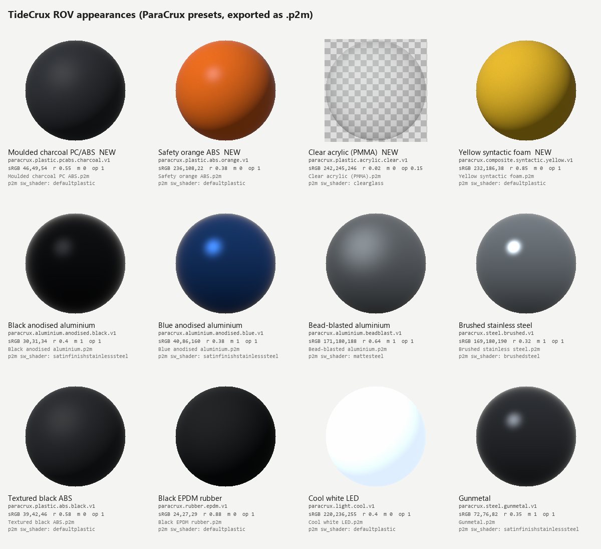
Fasteners, materials, appearances and profiles come from ParaCrux, not from one-off geometry, and parts are reused rather than rebuilt.
ParaCrux Toolbox · Global Standard
Fasteners in A4 stainless.
- ISO 4032 M4 hex nutA4-70
- ISO 4032 M5 hex nutA4-70
- ISO 4762 M3x8 socket head cap screwA4-70
- ISO 4762 M4x12 socket head cap screwA4-70
- ISO 4762 M5x20 socket head cap screwA4-70
- ISO 7089:2000 M5 washerA4
- ISO 7380-1 M5x10 button head screwA4-70
Generated from an approved library release as STEP, then made into SOLIDWORKS parts on the workstation with the ParaCrux material and the library stamp as custom properties. Volume matches the generator exactly. They are envelopes: threads are not modelled.
ParaCrux Materials
Real grades, one database.
- FairingPC+ABS – Bayblend T65 XF
- Frame tubeEN AW-6060 T66
- Housings, caps, trayEN AW-6061 T6
- Camera domePMMA (cast)
- SaddlesPOM-C
- Fasteners1.4401 X5CrNiMo17-12-2 sheet
- O-ringsSOLIDWORKS Rubber (stock)
The O-rings use the stock SOLIDWORKS rubber because the ParaCrux library has no elastomers yet. That gap is logged as MAT-GAP-01.
ParaCrux Profiles · part reuse
One tube, two ways.
The 25 × 2.0 mm aluminium round tube from the ParaCrux EN profiles is a structural member in the cross members, and the same section is swept along the bent frame.
Each part is cached under a SHA-256 key of its design parameters and builder code. A stage rebuilds a part only when its key changes, assemblies only place cached parts, and library hardware is converted once.
Then the brief changes: 300 m.
Re-rate it to 300 m and add a one-function gripper. Keep the frame footprint, battery and electronics tray. The design changes through catalogue choices in the parameter file, not by scaling.
| Item | TideCrux 100 | TideCrux 300 | Why (screening) |
|---|---|---|---|
| Rated depth | 100 m | 300 m | The change request |
| Housing | NPS 4 Sch 10 | NPS 4 Sch 40 | Sch 10 collapse margin falls to 2.75 ×, under the 3 × rule; Sch 40 gives 15.2 × |
| Housing wall | 3.05 mm | 6.02 mm | Follows the schedule through the housing equations |
| Camera dome | 6 mm PMMA | 10 mm PMMA | The membrane needs 9.4 mm at 300 m; a flat port would need 27.6 mm |
| Buoyancy foam | 200 kg/m³ | 400 kg/m³ | Shallow foam is not rated for 300 m; the deep grade is heavier, so more is needed |
| Gripper module | None | Fitted | The change request |
| Frame, tray, battery | Unchanged | Retained by the brief | |
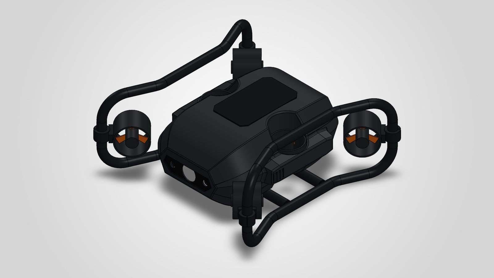
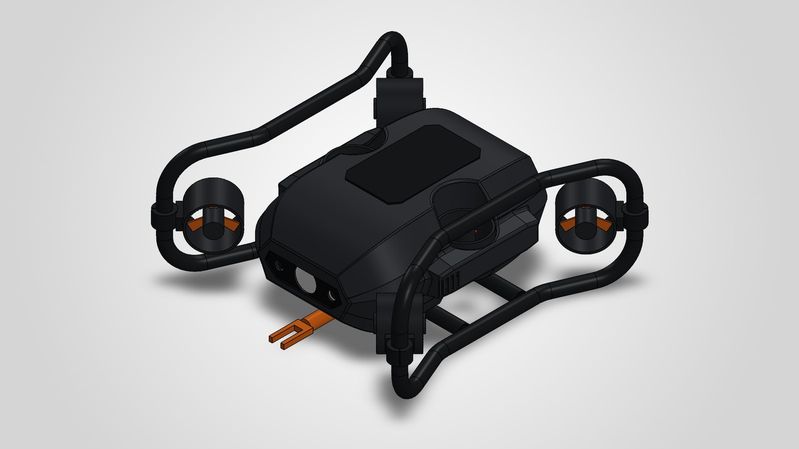
TC-301 (Main housing tube), TC-302 (Rear end cap), TC-303 (Front dome flange), TC-304 (Camera dome), TC-B10 (O-ring 106.2 x 3.53 NBR 70 (ISO 3601)), from the 300's values in the parameter file.
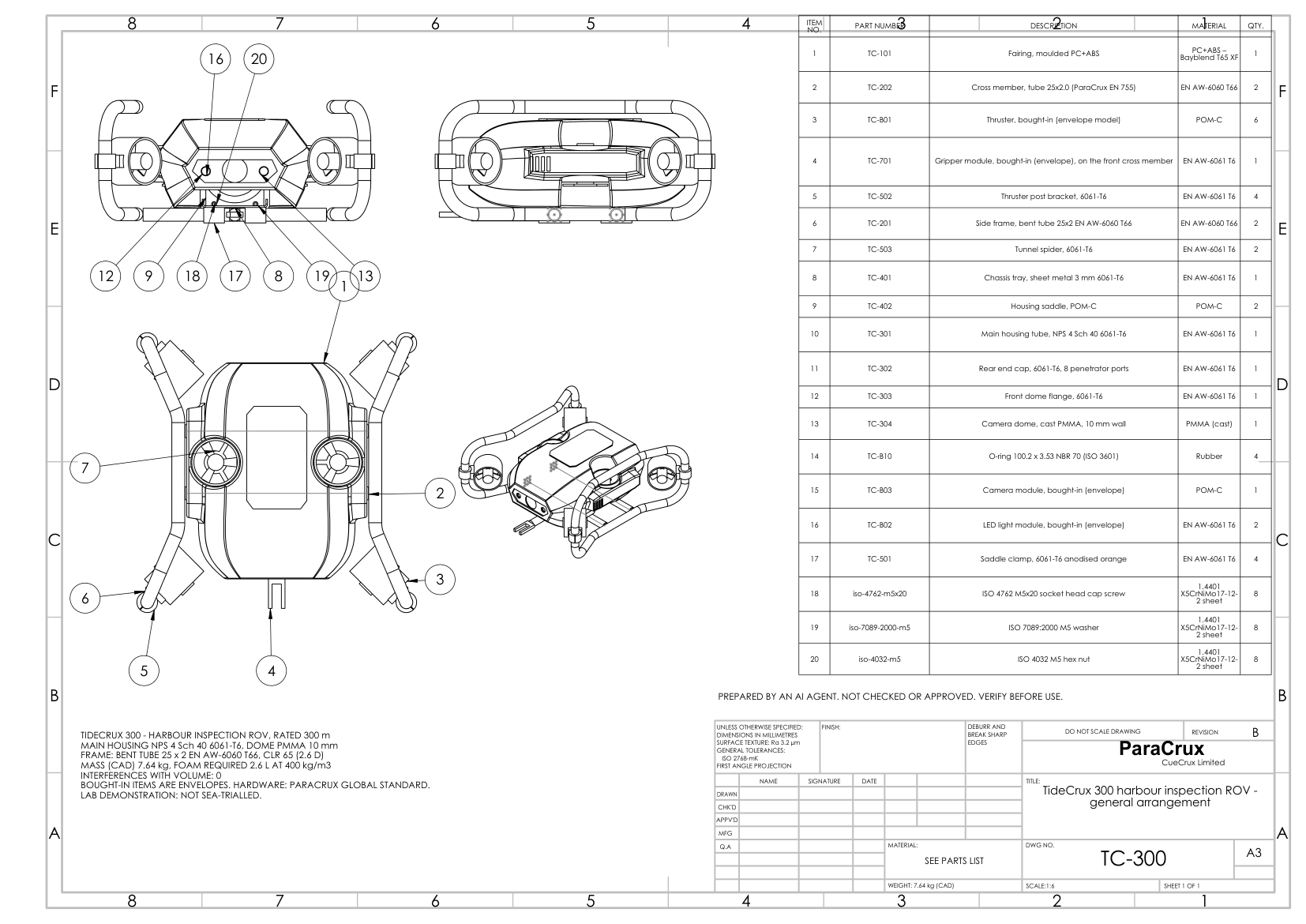
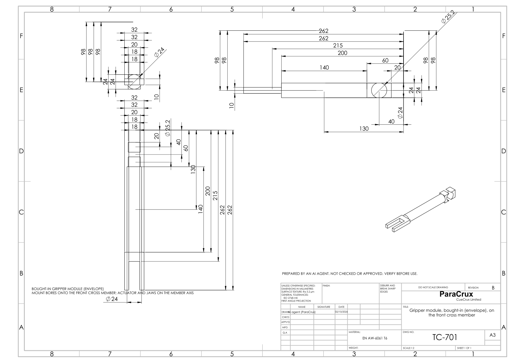
TC-701: Gripper module, bought-in (envelope), on the front cross member.
Unchanged parts come straight from the cache: the frame, fairing, tray and brackets are not rebuilt.
Editing "housing_wall" = 6.02 in TC-301 gives 491,480 mm³, the same as regenerating the part (491,480 mm³).
TideCrux 300 assembly, 60 components: no unexpected interferences. CAD mass 7.64 kg; −1.47 kg before foam, so 2.59 L of 400 kg/m³ foam is needed for +0.15 kg.
Drawn to BS 8888.
First-angle projection, ISO 2768-mK general tolerances, a parts list and balloons on the general arrangement, and a note on the sheet that it was prepared by an AI agent and has not been checked or approved.
TideCrux 100
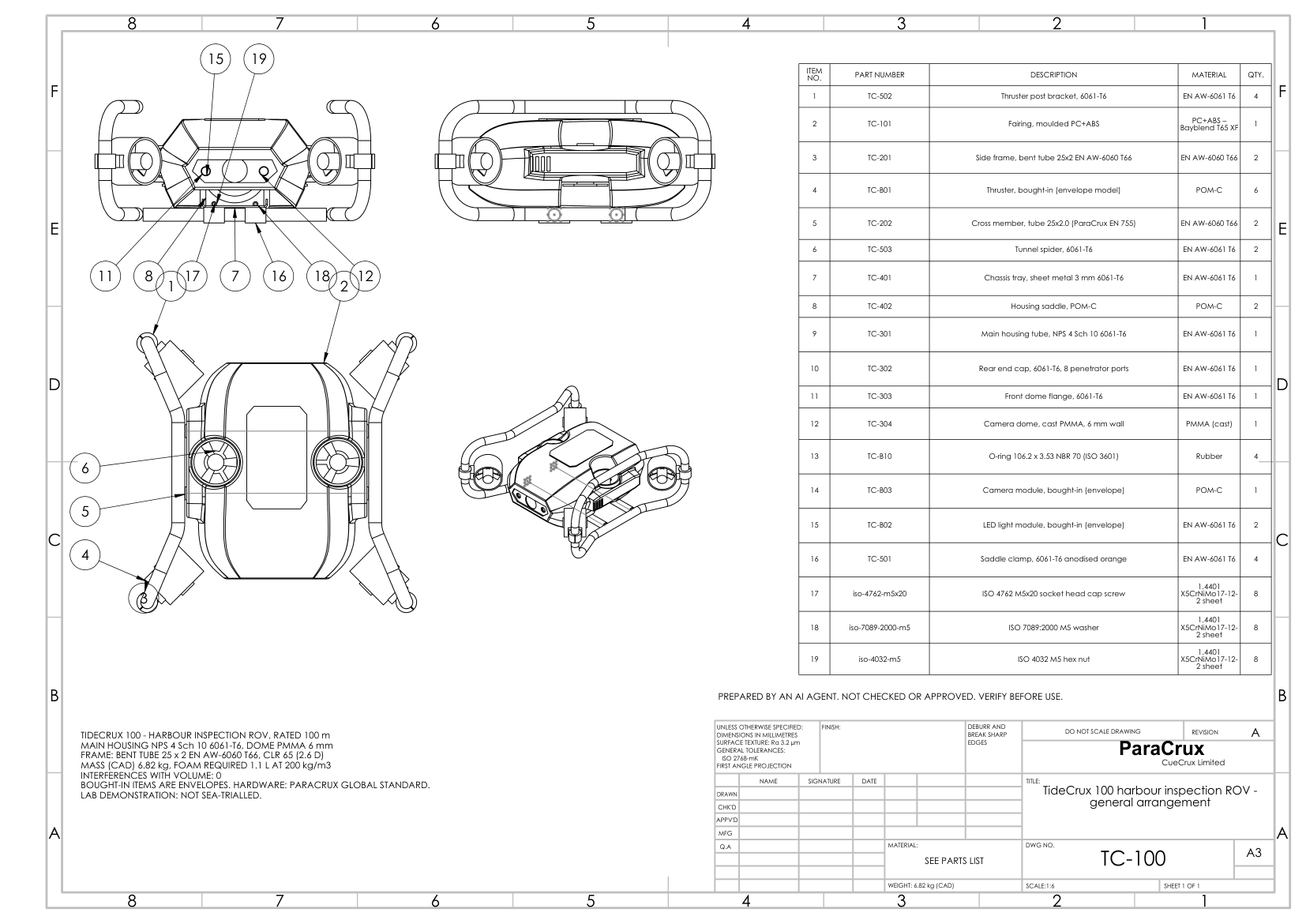 TC-100 general arrangement (PDF) ↗
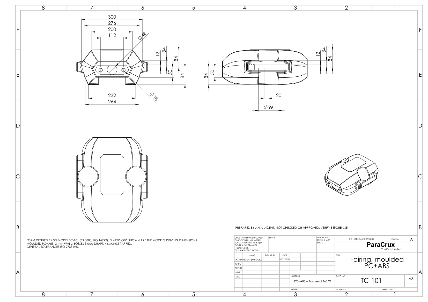 TC-101 · Fairing, moulded PC+ABS ↗
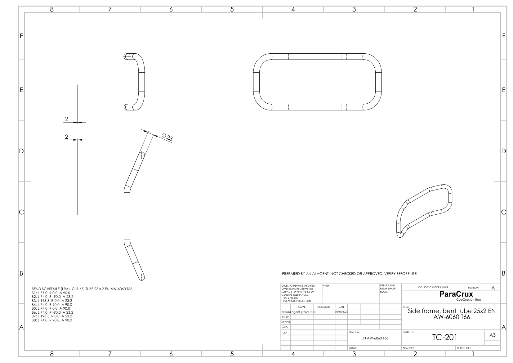 TC-201 · Side frame, bent tube 25x2 EN AW-6060 T66 ↗
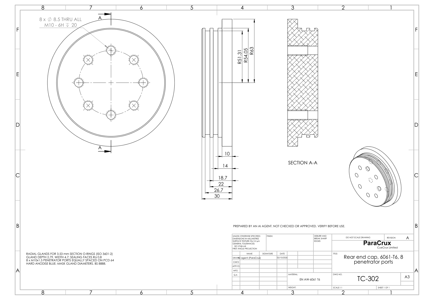 TC-302 · Rear end cap, 6061-T6, 8 penetrator ports ↗
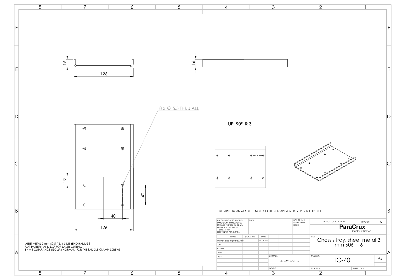 TC-401 · Chassis tray, sheet metal 3 mm 6061-T6 ↗
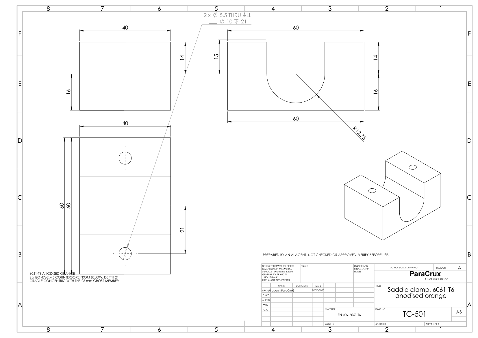 TC-501 · Saddle clamp, 6061-T6 anodised orange ↗
TideCrux 300
What this demonstrates, and what it doesn't.
An agent can model to a written standard, prove that its own audit catches a bad part, check the assembly and draw it, and say which requirements are still open. It does not show a vehicle ready for the water. There has been no hydrostatic proof test, tank trim or sea trial, and every pressure, buoyancy and drag figure is a screening calculation with stated assumptions. Thrusters, lights and the camera are envelope models, and the library fasteners have no threads. The O-rings use stock SOLIDWORKS rubber until the ParaCrux library has elastomers. Requirement R01 failed against its revision-0 envelope and was re-baselined.
See demo set one: ScoutCrux →See what the Agent ships today →Back to all demos →